Control Circuit Diagram Of Dol Starter
The contactor is responsible for controlling the flow of electricity to the motor, while the overload relay monitors and protects the motor from overloads. Web dol starter power circuit wiring diagram.
[Download 28+] Control Circuit Dol Starter Panel Wiring Diagram
Control Circuit Diagram Of Dol Starter. Electromagnetic contactor which can be opened by the thermal overload relay under fault conditions. Web this diagram will show how the components of the dol starter should be connected in order to create the desired control system. Web dol starter wiring diagram.
We Prefer A Direct Online Starter For Starting Of Small Rating Three Phase Induction Motors.
Web (a) (b) fig. Web direct online starter is method of starting of an induction motor. The dol starter is started by simply pressing the start push button and stopped by pressing stop push button.
Web Dol Starter Power Circuit Wiring Diagram.
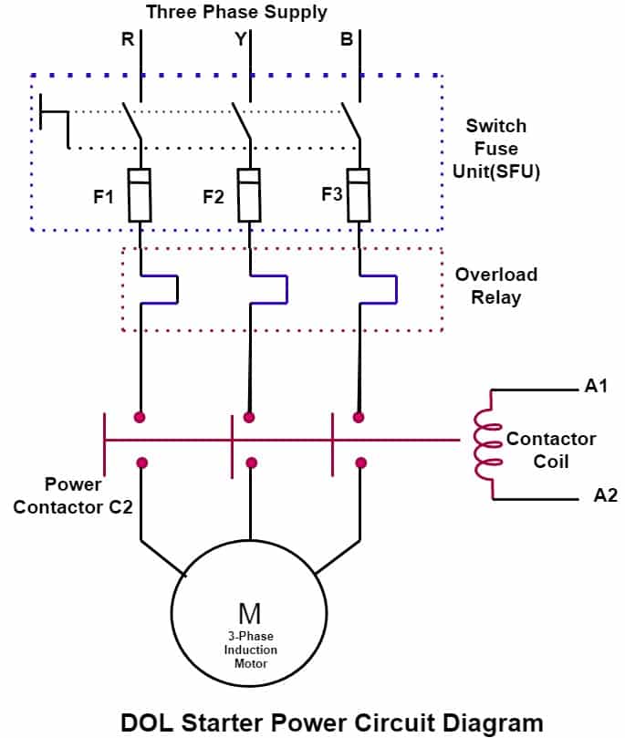
Web dol starter control circuit diagram consist components like main power contactor, start button, stop push button and overload relay is connected in series this circuit is called control circuit of dol motor starter. The direct on line motor starter (dol) consist a mccb or circuit breaker, contactor and an overload relay for protection. This diagram makes it easy to trace out how each component connects to the others and how it behaves under different scenarios.
Web 131 Share 10K Views 2 Years Ago #Dol This Video Is About The 3 Phase Dol Starter Control And Main Wiring Animation With Mccb, Magnetic Contactor, Thermal Overload Relay, Nc No Switches, Motor.
Features , advantages/disadvantages & applications of dol starter what is direct online (dol) starter? If the push button is pressed, the contactor gets energised and gets closed. Dol starter control and power wiring diagram.
Web Three Phase Dol Starter Wiring Diagram:
Dol starter (direct online starter) is also knows as “across the line starter”. Electromagnetic contactor which can be opened by the thermal overload relay under fault conditions. Web control circuit operation of dol starter induction motor using plc free electrical notebook theory and practical dol starter scheme and wiring diagram electric guider
The Wiring Diagram For A Dol Stater Is Shown Below.
(a) typical direct on line starter for small squirrel cage induction motor, (b) schematic wiring diagram for the control circuit thus, the motor gets connected across the supply mains. The dol starter comprises an mccb or circuit breaker, contactor and an overload relay for protection. Control circuit operation of dol starter induction motor using plc free electrical notebook theory and practical.
In This Circuit, We Use A Stop Switch, A Start Switch, An Sp Mcb ( Single Pole Miniature Circuit Breaker ), Tp Mcb ( Tripple Pole Minature Circuit Breaker ), A Magnetic Contactor, An Overload, Two Indicator Lights, A 3 Phase Motor.
Web dol starter circuit diagram dol starter working principle. A direct online starter consists of two buttons, a green button for starting and a red for stopping purpose of the motor. A to z learning dol starter connection three phase control overload indicator power wiring diagram facebook.
The Power Circuit Consists Of Mcb, A Main Contactor, And A Thermal Overload Relay Connected In Series With An Induction Motor.
It is widely used in a wide range of applications due to its flexibility and ease of use. Web dol starter control circuit wiring diagram. It includes every aspect of the system, from the power source to the motor itself.
Web Dol Starter Wiring Diagram.
The stator of the motor receives the full supply voltage in dol starter. It includes information about the types and sizes of wires, the connections between components, and the way the power supply is set up. Power circuit wiring of the starter is simple as shown in the above circuit diagram where l1, l2 and l3 are three phases.
This Method Has Easy Way Of Controlling The Device.
Web this diagram will show how the components of the dol starter should be connected in order to create the desired control system. Web troubleshooting three basic hardwired control circuits in starting electric motor eep. Electromagnetic contactor which can be opened by the thermal overload relay under fault conditions.
Innovations In Automation Technology Have Made It Possible To Regulate Both Voltage And Frequency Of An Appliance, Ensuring Reliable And Efficient.
Single phase dol starter wiring diagram: Web a dol starter control circuit diagram is an electrical schematic that shows how a motor or other device is connected to a power source. Web the direct on line motor starter (dol) consist a mccb or circuit breaker, contactor and an overload relay for protection.
Web A Typical Dol Starter Control Circuit Diagram Consists Of Several Components, Such As A Contactor, Overload Relay, On/Off Switch, And Timer.
The contactor is responsible for controlling the flow of electricity to the motor, while the overload relay monitors and protects the motor from overloads. Web a dol starter control circuit diagram is a visual representation of the wiring and components that make up a motor control circuit.

DOL Starter Circuit Control DiagramDiagram Electrical4u

Direct Online Starter DOL Starter, working,principle,Control,wiring
![[Download 28+] Control Circuit Dol Starter Panel Wiring Diagram](https://i2.wp.com/static-resources.imageservice.cloud/5137107/direct-online-starter-or-dol-motor-starter-electrical-technology.jpg)
[Download 28+] Control Circuit Dol Starter Panel Wiring Diagram

Dol Starter Wiring Diagram For Single Phase Motor for the men in

DOL Starter Electrical circuit diagram, Circuit diagram, Electric circuit
Dol Starter Motor Control Circuit Diagram

DOL starter control circuit diagram YouTube

DOL Starter Connection and Wiring Diagram with OLR ETechnoG
