Dc Servo Motor Circuit Diagram
The operation of a typical servo motor is explained in figure 1;depending on the duty cycle of the control signal, the servo motor will rotate to a specific position. We will cover some basics of controlling servos with one example that requires no programming at all.
AC Servo motor Working Principle, Circuit Diagram, Construction
Dc Servo Motor Circuit Diagram. Circuit diagram of ac servo motor. Web generally, the dc motor changes the energy from electrical to mechanical. Then we will control the servos with code using the arduino ide and python.
Web A Standard Servo Motor, Just As Other Motors, Are Essentially Just A Dc Motor, But With Some Extra Features:
Ac servo motor drive is the latest development of a new type of servo system, but also the current machine feeding drive system is a new trend.the system overcomes the shortcomings of the dc drive system, such as frequent maintenance of the motor brush and commutator, large motor. Now, let’s take a look at a dc servo motor driver circuit diagram. Web this tutorial covers a few different ways to control servos along with a project demonstrating how to control a servo from an external input.
Web Consider The Following Block Diagram Which Consists Of The Different Blocks Where The Function Of Each Block Is Explained In Brief.
Construction of ac servo motor similar to a normal induction motor, this motor comprises of a stator and a rotor. Model predictive control of dc servomotor using active set method | this paper presents the design and. Web a dc servo motor consists of a dc motor, a position sensing device, a gear assembly, and a control circuit.
Web Types Of Dc Servo Motor.
Web the dc servomotor diagram above is made up of two main parts, which are the electrical components (part labelled 1) and the mechanical components (part labelled 2). Dc servo motors can be controlled by using either the current of the field winding or the armature current. The microcontroller reads the position feedback information from the decoder and converts it into a velocity reading.
Web The Figure Below Shows The Schematic Diagram For An Armature Controlled Dc Servo Motor.
Holding position with a servo. The ground wire is typically black or brown and should be connected to a ground pin on the board. Then we will control the servos with code using the arduino ide and python.
Web To Begin, We’ll Need To Look At The Three Main Parts Of The Dc Servo Motor Circuit Diagram:
The power source, the control board, and the servo motor itself. Note that an armature control current is created when the armature control voltage, va, energizes the motor. The great thing about a servo is it can be configured to hold its position between actuation steps.
Now, A Dc Reference Voltage Is Set To The Corresponding Desired Output.
The current flow through a series. The electrical components consists of resistance, inductance, input voltage and the back. Accordingly, they are classified as:
Circuit Diagram Of Ac Servo Motor.
Web generally, the dc motor changes the energy from electrical to mechanical. The operation of a typical servo motor is explained in figure 1;depending on the duty cycle of the control signal, the servo motor will rotate to a specific position. Plant consists of a dc motor with an inertial load.
Control Circuit For Controlling The Motor, E.g.
Gears that transform speed into torque, which makes it capable of doing heavy lifting at a slower speed, as opposed to a regular dc motor that just spins very fast! Here the armature is energized by amplified error signal and field is excited by a constant current source. The holding torque provided by a servo motor is comparable to that from a stepper motor.
Web Download Scientific Diagram | Electrical Circuit Diagram Of Dc Servomotor From Publication:
The dc motor is separately excited and armature controlled, which schematic diagram is shown in fig. Field controlled dc servo motors, armature controlled dc servo motors. Web figure 2 shows that a dc servomotor has two main components, the electrical and the mechanical components.
We Will Cover Some Basics Of Controlling Servos With One Example That Requires No Programming At All.
The controller then adjusts the signal to the servo motor to cancel out any error. Stator of ac servo motor the stator of this motor which has a laminated structure, is wound with its two windings placed 90 electrical degrees apart in space. Dc servo motor driver circuit diagram.
A Block Diagram Of A Typical Dc Servo System Is Shown In Figure 1.
Derive the dc servomotor electromechanical transfer function. The field is operated at well beyond the knee point of magnetizing saturation curve. The dc servo motor has a small dc motor is employed for driving the loads at a precise speed and position.
Figure 1 Dc Servo Motor Block Diagram.
Armature controlled dc servo motor block diagram. Unlike direct current (dc) motors, the dc servo motor’s angular position can be adjusted to a specific angle by using a control signal. Web ac servo motor controller circuit diagram.
Servo Motors Are Widely Used In Different Types Of Applications And Suitable For Movement Or Rotation Based Mechatronic Needs.
The power source provides the energy needed to run the motor which is fed through the control board. Web the servo motor is an electric actuator thatcan be positioned in a desired angle from 0° to 180°. Web servo motor basics and controll ciruits diagram.pdf engr rana m shakeel the dc motor sends out encoded position signals to the quadrature decoder chip.
Arduino Has Recently Been Used In A Wide Range.
Web draw the dc servomotor signal block diagram. Web the controller compares the setting to the measured result and calculates the error. Web servo motor driver circuit december 7, 2018 admin 3 comments here sub micro size servo motor is taken as a target device and we developed servo motor driver circuit for that motor.
Web By Changing The Width And Frequency Of The Pulses, The Dc Servo Motor Driver Circuit Can Precisely Control The Speed And Direction Of The Motor.
Circuit theory model the circuit shown in figure 2 models the dc servomotor. Web block diagram showing how to drive a servo motor with a motor controller ic. The power wire is typically red, and should be connected to the 5v pin on the arduino board.
The Supplied Electrical Energy At The Armature Terminals Is Changed Into Controlled Mechanical Energy.
This diagram shows the various components of the circuit and how they are connected.

DC Servo motor Theory, Circuit Diagram, Types, Characteristics

How does a Servo Motor work? CircuitBread

DC Servo motor Theory, Circuit Diagram, Types, Characteristics

DC servo motor block diagram. Download Scientific Diagram

100 watt DC servo amplifier circuit using Power MOSFET

35 The principle of operation for DC servo motor Download Scientific

DC motor servo circuit composed of μA741 Basic_Circuit Circuit
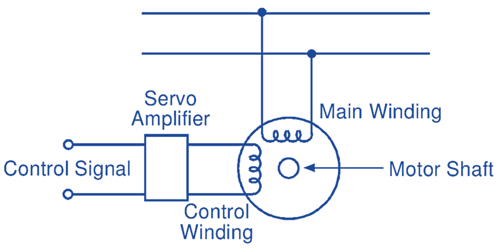
AC Servo motor Working Principle, Circuit Diagram, Construction
