Difference Between Schematic And Circuit Diagram
A schematic represents circuit elements with symbols and connections as lines. Although schematic diagrams are commonly associated with electrical circuits, many examples can be found in other industries.
Connector Symbol Wiring Er Diagram Major Tilghman
Difference Between Schematic And Circuit Diagram. These two different types of circuit diagrams are called pictorial (using basic images) or schematic style (using industry standard symbols). Differences between schematic diagram and pictorial diagram; After seeing a few circuit diagrams, you’ll quickly learn how to distinguish the different symbols.
It Is Vital For A Pcb Designer To Get Familiarized With The Schematic Symbols That Represent The Components On A Schematic Diagram.
Ladder diagrams show how a circuit works logically and electrically. Web a circuit diagram is different from a circuit schematic in that it shows a more granular view of how fundamental circuit elements (e.g., transistors, resistors, etc.) are combined to form an ic. Web wiring diagrams refer to diagrams of how components are connected together to form an electrical circuit.
Web In An Electronic Circuit Diagram, The Layout Of The Symbols May Not Look Anything Like The Circuit As It Appears In The Physical World:
Wiring diagrams one of the most frequently used diagrams in motor control work is the ladder diagram, also known as a schematic diagram. Web difference between schematics and circuit diagrams differences between schematic diagrams and circuit diagrams. Schematics is readable and understandable format about the connectivity and functionality between different components.
These Two Different Types Of Circuit Diagrams Are Called Pictorial (Using Basic Images) Or Schematic Style (Using Industry Standard Symbols).
What is the difference between circuit diagram and schematic diagram? These diagrams include information about power connections and simple information about the signal flow. It is a way of communicating to other engineers exactly what components are involved in a circuit as well as how they are connected.
A Single Cell, Light Bulb And Switch Are Placed Together In A Circuit Such That The Switch Can Be Opened And Closed To Turn The Light Bulb On.
Web schematics/circuit diagram conveys the electrical connection between different active and passive electrical components like resistors, capacitors, integrated circuits ic. As an adjective schematic is represented simply. Web a schematic diagram is a picture that represents the components of a process, device, or other object using abstract, often standardized symbols and lines.
After Seeing A Few Circuit Diagrams, You’ll Quickly Learn How To Distinguish The Different Symbols.
Web is that schematic is a drawing or sketch showing how a system works at an abstract level while diagram is a plan, drawing, sketch or outline to show how something works, or show the relationships between the parts of a whole. How to make schematic diagram in edrawmax; Differences between schematic diagram and circuit diagram;
Instead Of Representing The Way The Circuit Looks, The Schematic Aims To Capture, On A More General Level, The Way It Works.
It serves as a visual tool for the design, construction, and maintenance. Symbol usage depends on the audience viewing the diagram. Web a schematic shows connections in a circuit in a way that is clear and standardized.
Web A Wiring Diagram Is A Simple Visual Representation Of An Electrical System's Or Circuit's Physical Connections And Layout.
Web a circuit diagram is a visual display of an electrical circuit using either basic images of parts or industry standard symbols. In contrast, your circuit schematic will bunch a more complex circuit diagram for an ic into a single box with inputs and outputs. This schematic shows a simple circuit, which includes a battery and a switch schematics can also be used in repair.
As A Verb Diagram Is To Represent Or Indicate Something Using A Diagram.
Web a circuit diagram, also known as an electrical diagram, elementary diagram, or electronic schematic, is a graphical representation that simplifies an electrical circuit. It illustrates how electrical wires are connected and where components are actually connected to the system. On the other hand, a schematic diagram is a graphical representation of all the components and their corresponding.
What Are The Main Differences Between Wiring Diagrams & Schematic Diagrams
Although schematic diagrams are commonly associated with electrical circuits, many examples can be found in other industries. A schematic, or schematic diagram, represents the elements of a system. Web the main difference between a wiring diagram and a block diagram is that wiring diagrams are mainly used in electrical applications.
Web A Circuit Diagram, Or A Schematic Diagram, Is A Technical Drawing Of How To Connect Electronic Components To Get A Certain Function.
Web a schematic is a drawing of a circuit. Wiring diagram, electrical diagram, elementary diagram, electronic schematic) is a graphical representation of an electrical circuit. A pictorial circuit diagram uses simple images of components, while a schematic diagram shows the components and interconnections of the circuit using standardized symbolic representations.
Use Circuit Symbols To Construct Schematic Diagrams For The Following Circuits:
Web use cases of schematic diagrams; Differences between schematic diagram and pictorial diagram; This diagrams uses symbols to identify components and interconnecting lines to display the electrical continuity of a circuit.
Web One Major Difference Between The Two Is That With A Circuit Diagram, You Can Easily Identify And Trace The Connections Between Components.
Is a schematic that shows how components. Each electronic component has a symbol. A schematic represents circuit elements with symbols and connections as lines.
What To Do Before Creating A Schematic Diagram;
Web a circuit diagram (or: With schematics, it is much more difficult to trace the wiring paths, as components are often grouped together to. Schematics and circuit diagrams are commonly used in.

Explain Schematic And Wiring Diagrams Circuit Diagram

explain the difference between a wiring diagram and a circuit diagram

DIFFERENCE BETWEEN SCHEMATIC AND WIRING DIAGRAM Stem Inspire
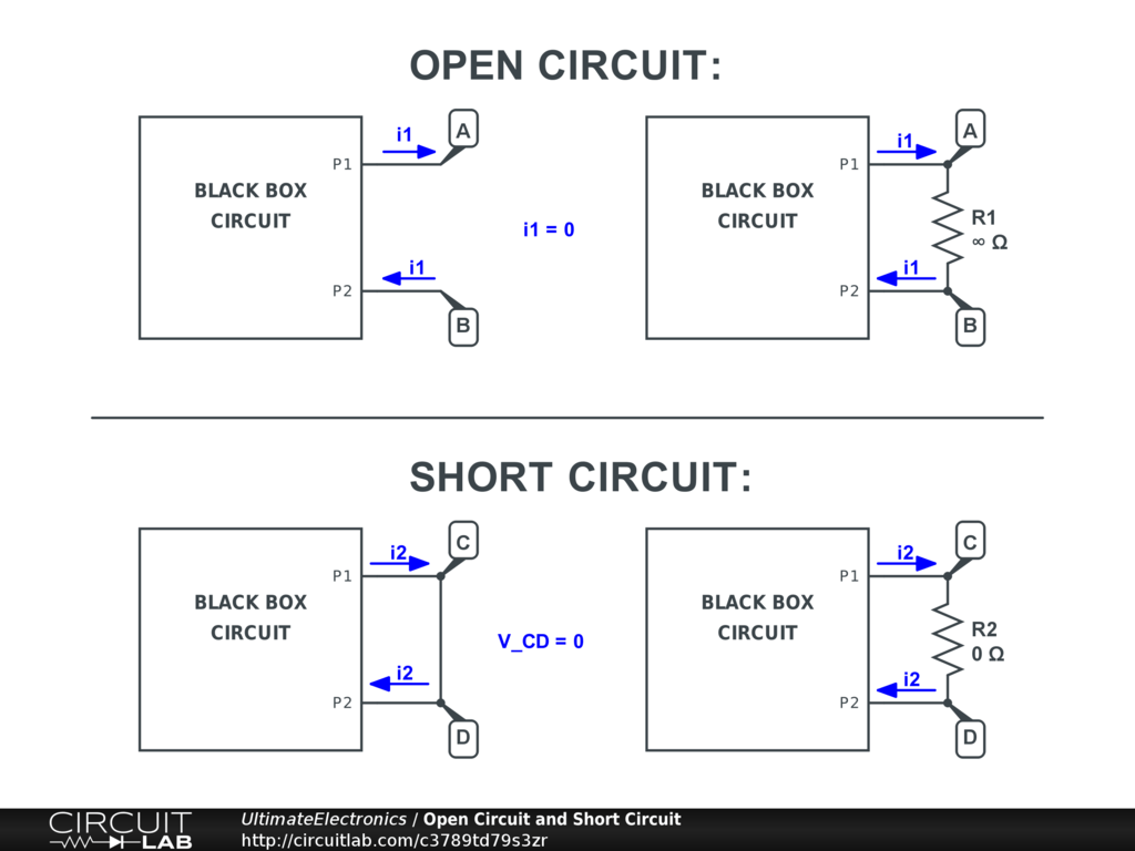
Open Circuit and Short Circuit Ultimate Electronics Textbook

Schematic vs. Wiring Diagrams Basic Motor Control

Connector Symbol Wiring Er Diagram Major Tilghman

L2 Circuit Schematics Physical Computing

explain the difference between a wiring diagram and a circuit diagram
