Digital Clock Circuit Diagram Pdf
Thearchitectural design was carried out using synchronousdecade counters and logic gates. Circuit diagram the following circuit is a schematic of the logic diagram for the binary clock which is going to be implemented.
Digital Stop Watch Simple Projects
Digital Clock Circuit Diagram Pdf. Web digital clocks, (iii) auditory clocks (iv) textual clocks. They are i) analog clocks, ii) digital clocks, iii) auditory clocks, iv) textual clocks. Thearchitectural design was carried out using synchronousdecade counters and logic gates.
Web Pdf | The Aim Of The Project Is To Design A Twelve Hour Digital Clock That Displays The Time Digitally, In Contrast To An Analog Clock, Where The Time.
Thearchitectural design was carried out using synchronousdecade counters and logic gates. Web here's a circuit diagram for the power supply and time base. I have only used ic’s but still got a 12 hour clock, which i’ve not seen elsewhere.
3 74Hc393 Ic 2 74Hc08 Ic
Web digital clock circuit diagram. Two numeric display formats are commonly used on digital clocks. Web digital clocks, (iii) auditory clocks (iv) textual clocks.
To Create The Rest Of The Clock You Will Need:
Once reducing the activity of the clock. Circuit diagram the following circuit is a schematic of the logic diagram for the binary clock which is going to be implemented. Click hints if you need help to design the 24h clock.
At Least Four 7490 Or 74Ls90 Chips.
| find, read and cite all the research. They are i) analog clocks, ii) digital clocks, iii) auditory clocks, iv) textual clocks. Web pdf | the aim of the project is to design a twelve hour digital clock that displays the time digitally, in contrast to an analog clock, where the time.
The Above Circuit Consists Of 4 Seven Segment Display Driver Ic 4026 Which Can Display 0 To 9 On Common Cathode 7 Segment Display, One Ic Controls One 7 Segment Display.
In this paper the design, implementationand simulation of a digital clock capable of displayingseconds, minutes and 24 hours timing is presented. Digital clocks display a numeric representation of time. Web clock system architecture for digital circuits amit saxena, kshitij shinghal, rajul misra and alok agarwal 1 introduction in digital synchronous circuits, a periodic clock is generally used to synchronize or provide timing to the circuit.
Of The Phase Error Between Incoming Data And Recovered Clock(Rck).
Web the sequential circuits of digital the general circuit diagram of 24 hours digital electronics were implemented to design the clock. As we saw in the article on electronic gates, the power supply is the most difficult part! | find, read and cite all the research you.
This Paper Is Based On Multisim 12.0 Digital Clock Design And Simulation, Focusing On The Working Principle Of Digital Clock, Analysis And Design Of Digital Clock Circuit.
Web in a synchronous digital system, the activity of the clock signal is a major energy consumer. Web sizes of clocks are available. Two numeric display formats are commonly used on digital clocks.
It Is Responsible For 15% To 45% Of The Total Consumed Energy.
Web abstract—this paper takes altera ep4ce6e22c8n as the control center, and designs a multifunctional digital clock system based on fpga, which consists of clock module, timing module, power module, keyboard control module, data decoding module and digital tube display module hdl designs text input for the system logic description language. There is an accelerated interest in teaching Web circuit diagram for 7 segment display digital clock:
Most Digital Clocks Use An Lcd Or Led Display.
The filtered control voltage (vf)drivesthevoltage controlled oscillator (vco) toward phase lock. I’ve also added a small alarm module. Web of this digital clock mini project with circuit diagram can be taken as with ease as picked to act.
Digital Clocks Display A Numeric Representation Of Time.
We will explain the steps to arrive at the combinational logic to obtain a 12h clock and we will leave it to the reader to design the 24h clock as an exercise. Web the clock can be designed as a 24h or 12h clock. Logic circuit using logic gates for a binary clock [7] b.
Download High Resolution Image Of The Above Circuit Diagram:
The output for generating an alarm signal at pin 16. Components required the components required for this circuit are as follows: | find, read and cite all the research you.
Web Pdf | The System That Is Anticipated To Be Built Consists Of A 6 Digit Clock Including Hour, Minute And Second Using A Very Cheap Devices That Covers A.
Web as may be witnessed in the given diagram the heart of the circuit is formed by the ic1 (lm8560), which is assigned with the following outputs terminals: Depending on the method of time display, clocks can be classified by four types.
LM8560 Digital clock circuit diagram with alarm

Digital Stop Watch Simple Projects

simpledigitalclockusinglm8650iccircuit.png

LM8365 digital clock circuit board in 2021 Circuit

Digital Clock Circuit with Seconds and Alarm Time Display Engineering

24Hour Digital Clock and Timer Circuit Best Engineering Projects

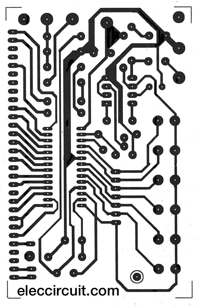
Circuit Diagram Of Digital Clock PCB

Digital Clock Circuit Using IC 555 and IC 4026 DIY Electronics Projects
