Digital Combination Lock Circuit Diagram
Web so i drew this diagram as a map to guide me as i build each part of the proyect. K1 = 12v spdt relay / any appropriate relay with 12v coil;
door lock circuit Page 3 Security Circuits Next.gr
Digital Combination Lock Circuit Diagram. Web circuit elements and implemented with digital electronic logic gates. Row pins r1 to r4 are interfaced to digital pins 6 to 9 of the arduino. To gain access to the lock, you must.
This Is The Circuit Diagram Of A Simple Electronic Combination Lock Using Ic Ls 7220.This Circuit Uses A Relay For Controlling Any Type Of Device When The Combinations Of Four Digits Are Pressed.keypads Are Used As Input Here To Enter The Digits And The Correct Combination Will Activate The Relay And The Door Or Deice Can Be Operated.
This relay can then be __ designed by aaron cake. Digital code lock project using 8051 microcontroller. Password door lock security system using arduino and keypad.
A Simple Electronic Combination Lock Is Designed Using Ic Ls 7220.
To gain access to the lock, you must. Web digital code lock circuit diagram: Web the digital combinational lock presented in this paper is equipped with advanced features wherein the user can set the combination of his or her choice “n” number of times.
Web Digital Combination Lock 7 Steps With Pictures Instructables.
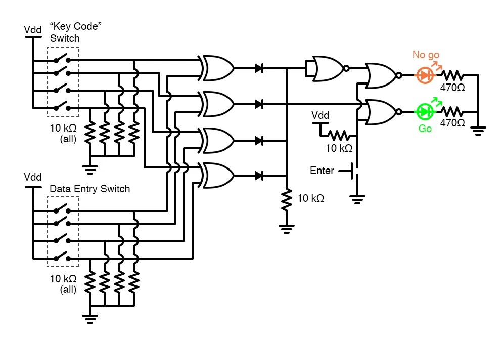
Using the special purpose ls7220 digital lock ic , the circuit allows a 4 digit combination of your choice to activate a relay for a set period of time. Set the key code for the system by configuring the four key code switches. Row pins r1 to r4 are interfaced to digital pins 6 to 9 of the arduino.
The Circuit Above Makes Use Of The Cmos 4017 Decade Counter Ic.
Web the digital lock shown below uses 4 common logic ics to allow controlling a relay by entering a 4 digit number on a keypad. The first 4 outputs from the cd4017 decade counter (pins 3,2,4,7) are gated together with 4 digits from a keypad so that as the keys are depressed in the correct order, the counter will advance. Q1 = 2n3904 / 2n2222;
Web So I Drew This Diagram As A Map To Guide Me As I Build Each Part Of The Proyect.
Web a design of a digital combination lock system which investigates a finite state machine based combination (digital) lock using several modules. Column pins c1 to c4 are interfaced to digital pins 10 to 13 of the arduino. Web this could be the circuit diagram of a easy electronic combination lock by using ic ls 7220.this circuit may be applied to activate a relay for controlling (on & off) any device each time a preset combination of 4 digits are pressed.the circuit may be.
When The Push Buttons Are Pressed It Connects The Input To Vcc.
Web circuit elements and implemented with digital electronic logic gates. The working of the above circuit is split into different blocks and explained individually. U1 = ls7220 digital lock ic;
The Paper Focuses On The Implementation Of A Coded Keyless Lock.
This circuit can be used to activate a relay for controlling (on & off) any device when a preset combination of 4 digits are pressed. Simple electronic combination lock schematic diagram. Web april 4, 2020.
The Block Diagram Of The Power Supply Unit, The Input, Control And The Output Units Are Shown In The Figure Below (Fig.
Web this is the circuit diagram of a simple electronic combination lock using ic ls 7220.this circuit can be used to activate a relay for controlling (on & off) any device when a preset combination of 4 digits are pressed.the circuit can be operated from 5v to 12v. Web digital combination lock diagram to see the clear view, click on it or save this diagram on your pc by right click on this and choose save pictures as notes: Web this section deals with the design procedure for the electronic combination lock.
Web Schematic Diagram Of The Digital Combination Lock With Led Output Indicators.
We are using general purpose push buttons to feed input to the circuit. Electronic combination lock with pic. Web the following diagram is a very easy and simple electronic combination lock based on ic ls7220.
K1 = 12V Spdt Relay / Any Appropriate Relay With 12V Coil;
Web the following diagram is a very easy and simple electronic combination lock based on ic ls7220. Heres a summary of how it works. Digital pin 3 of the arduino is configured as the output pin.
Jk Flip Flop Cd4027B Circuit Pinout And Datasheet Easybom.
A combinational lock access control system is a critical link in a security chain.

Digital code lock

Electronic Combination Lock Circuit using IC LS 7220

Digital combination lock

Help with combination lock circuit All About Circuits

door lock circuit Page 3 Security Circuits Next.gr

Digital Combination Lock Circuit Diagram Project Tutorial Alarms

Simple Electronic Code Lock CircuitsProjects
Digital Lab Digital Combination Lock Digital IC Projects
