Digital Voltmeter Circuit Diagram
The range can be appropriately widened or shortened simply by altering the value of the 1m resistor positioned in series with the input terminal. Web let’s build an icl7107 digital voltmeter circuit.
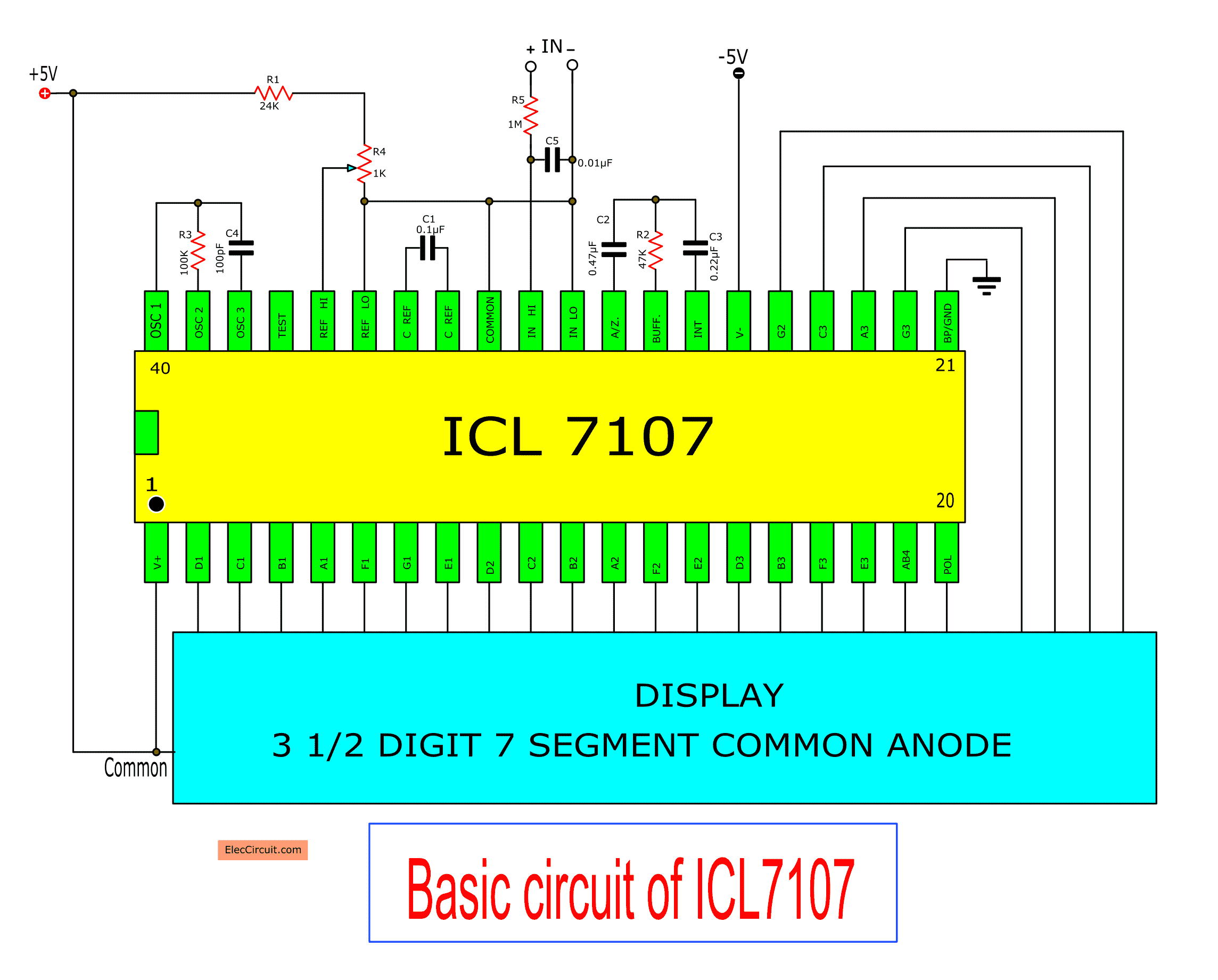
Digital voltmeter circuit diagram using ICL7107 / 7106 with PCB
Digital Voltmeter Circuit Diagram. Web circuit diagram of digital voltmeter using using icl7107; Web in this article, we will discuss the implementation of a digital voltmeter using 8051 microcontroller. Web so, the analog voltmeter doesn't require an additional power supply, because the voltage is reflected by moving a pointer across a scale, which is moving due the magnetic field changes, but digital voltmeter requires battery for.
Here Portb Of Atmega32 Is Connected To Data Port Of Lcd.
Web the circuit diagram for a direct coupled amplifier dc voltmeter using cascaded transistors is shown in figure. Using icl7107, we can build accurate and very low cost voltmeter. Vtvms and fet vms 3.
The Range Can Be Appropriately Widened Or Shortened Simply By Altering The Value Of The 1M Resistor Positioned In Series With The Input Terminal.
Web the figure below shows the block diagram of a typical digital voltmeter. Now building a digital voltmeter circuit does not need high technology and a big circuit. An attenuator is used in input stage to select voltage range.
Web Talking About The Circuit Diagram Below, The Unit Is A Complete Fledged Digital Voltmeter Circuit That Are Available For Calculating Direct Voltages Starting From Zero To 199 Volts.
Web the below picture shows the block diagram of the digital voltmeter. Circuit diagram of digital voltmeter using 8051 microcontroller; The basic circuit of one type of analog electronic voltmeter is illustrated in figure 1.
This Adc Unit Basically Distinguishes Between Various Types Of.
These are of like moving iron, moving coil, electrostatic types of voltmeters. The voltage at their junction is buffered by t1, and then passed to reference diode d1 via r3. Voltmeter is a measuring instrument, used to measure the voltage difference between two points in electrical network.
Web Referring To The Circuit Diagram Below, The Unit Is A Full Fledged Digital Voltmeter Circuit Which Can Be Used For Measuring Direct Voltages Right From Zero To 199 Volts.
Icl7107 ic common anode led display (dl1, dl2, dl3, dl4 = man 6960) breadboard jumper wires resistors. Stacking up five ip camera reference designs; Analog voltmeters analog voltmeter includes deflecting type of indicating voltmeters.
A Digital Voltmeter Provides A Numerical Display.
In this article, we will discuss the implementation details of modifying the digital voltmeter using the stm8s003f3 microcontroller additionally used as continuity and circuit tester, along with the project source code. 3 digit digital voltmeter based on the voltage range selected by the user, the unknown analog input signal is first attenuated. The range could be properly broadened or hardened easily by changing the value of the 1m resistor placed in series with the input terminal.
Using 3D Electronic Component Models To Synch Pcb And Enclosure Designs;
Web a voltmeter is an instrument that measures the difference in electrical potential between two points in an electric circuit. Here we are using a very popular ic for voltage measurement namely icl7107/cs7107. Web here each resistor r1 to r4 drops certain voltage from input and these drop voltage given to the comparator operational amplifiers, led1 and led2 indicates the voltage level upto 12 volt, at the lowest range led7 and led8 indicates less than 3 volt input.
The Complete Digital Voltmeter Circuit Diagram Is Shown In The Above Figure.
The 8051 microcontroller is a widely used microcontroller, which is suitable for a variety of applications. Introduction electrical parameters like voltage and current are inherently associated with electronics and with electronic engineers. Web circuit diagram of digital voltmeter using using icl7107;
Moving Coil Instruments Are Of Two Types Namely Permanent Magnet And Dynamo Meter Types
This particular circuit is made up of three stages: An analog voltmeter moves a pointer across a scale in proportion to the circuit’s voltage; Web circuit diagram of digital voltmeter using 8051 microcontroller circuit diagram of voltmeter, continuity & digital lcd circuit tester components required to build a digital voltmeter using the icl7107, we need the following components:
Web October 6, 2018 In This Project, I’ll Show How To Design A Digital Voltmeter Using 8051 Microcontroller And Also Explain Its Working.
Web so, the analog voltmeter doesn't require an additional power supply, because the voltage is reflected by moving a pointer across a scale, which is moving due the magnetic field changes, but digital voltmeter requires battery for. As we can see, the block diagram consists of attenuator with an analogue to digital converter after it. Digital voltmeter circuit diagram using icl7107 / 7106 with pcb
Web Simple Digital Voltmeter Circuit Using Icl7107.
Web circuit or block diagram of digital voltmeters: Block diagram of digital voltmeter working principle of digital voltmeters: Web circuit diagram and working explanation.
Web In This Article We Learn How To Build A Digital Voltmeter And A Digital Ammeter Combined Circuit Module For Measuring Dc Volts And Current Through Different Ranges, Digitally.
A transistor is a current controlled device so resistance is inserted in series with the transistor q 1 to select the voltage range. Dual slope type dvm 3. From the above block diagram, the voltage to be measured is given to the input signal present in the circuit diagram.
Make A Digital Voltmeter Using An Arduino;
In this project we are going to build a digital voltmeter without using any microcontroller. Thirty years ago, we created this circuit very difficult. Electronic voltmeter circuit diagram (block diagram)
Web In This Article, We Will Discuss The Implementation Of A Digital Voltmeter Using 8051 Microcontroller.
Web an rms detector for a wideband voltmeter—design and operation; It is an important basis for other measurement tools circuits. Web let’s build an icl7107 digital voltmeter circuit.
An Input Attenuator, An Electronic Amplifier, And An Electromechanical Voltmeter Stage.
Digital voltmeter circuit diagram using ICL7107 / 7106 with PCB

Digital voltmeter circuit diagram using ICL7107 / 7106 with PCB

Simple Digital Voltmeter Circuit Diagram using ICL7107

Digital voltmeter circuit diagram using ICL7107 / 7106 with PCB

ELEX IDEA BLOG Digital voltmeter using ICL7107

ICL7107 Digital Voltmeter

ICL7107 Digital Voltmeter

Make this Simple Digital Voltmeter Circuit Using IC L7107 Circuit
